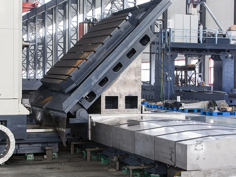
CNC Planer Type Boring Mill (Heavy Duty Boring Mill)
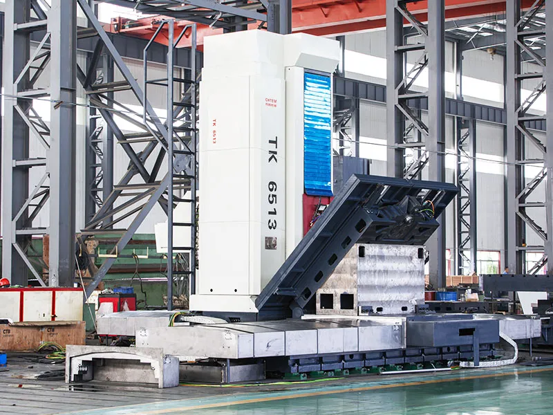
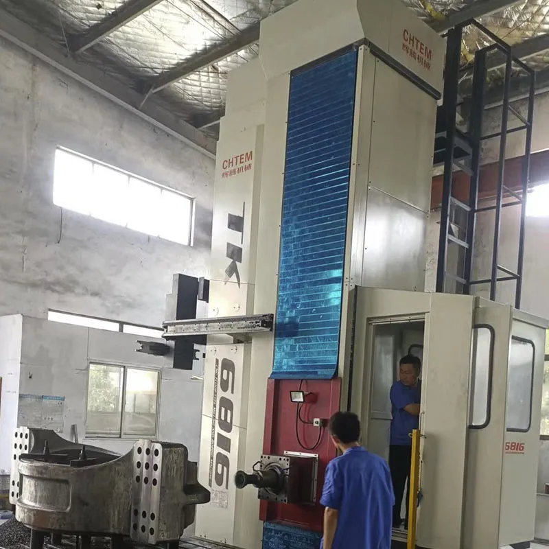
CNC planer type boring and milling machine is suitable for the processing of large and medium-sized box-type parts, frame-type components, and mold parts. After a single clamping of the workpiece, the machine automatically completes milling, boring, drilling, reaming, countersinking, and tapping operations. It can achieve seven-axis control and four-axis simultaneous linkage, performing circular interpolation and 3D curved surface machining. The spindle uses a cooling jacket to control spindle temperature rise.
The X-axis and Z-axis travel of this equipment can be designed according to customer requirements; the Y-axis travel does not exceed 3 meters; the W-axis travel is 1 meter. The tool magazine can accommodate up to 40 tools. This CNC machine can be configured with different systems, different precision levels, and different rotary table sizes to form different grades and specifications of machine tools.
This machine is widely used for the machining of box-type components, frame structures, and mold parts.
| Models | TK6511 | TK6513 | TK6516 | TK6813 | TK6816 |
| Headstock & Ram | |||||
| Spindle Diameter [mm] | ∅110 | ∅130 | ∅160 | ∅130 | ∅160 |
| Spindle Taper [ISO] | 50 | ||||
| Spindle Speed [rpm] | 10-2000 | 2-2000 | 2-2000 | 2-2000 | 2-2000 |
| Milling Head Diameter [mm] | ∅221.44 | ∅221.44 | ∅250 | ∅221.44 | ∅250 |
| Cross Section of Ram [mm] | / | / | / | 400×400 450×450 480×480 |
450×450 |
| Worktable Size [mm] | 1200×1400 1400×1600 |
1400×1600 1600×1800 |
1400×1600 1600×1800 1800×2000 |
1400×1600 1600×1800 1800×2000 2000×2500 |
1400×1600 1600×1800 1800×2000 2000×2500 2500×3000 |
| Max. Load Capacity of Worktable (Adjustable) [kg] | 6000-20000 | 10000-30000 | 20000-50000 | 10000-40000 | 20000-60000 |
| Distance Between Spindle Center and Worktable Surface [mm] | -25 | ||||
| Min. Distance from Spindle to Worktable [mm] | 0 | ||||
| Main Motor Power [kW] | 17/22.5 | 22/30 | 30/41 | 30/41 | 37/51 |
| Working Area | |||||
| Travel of Worktable (X-Axis) (Adjustable) [mm] | 2000 | Designed to requirements | Designed to requirements | Designed to requirements | Designed to requirements |
| Vertical Travel of Headstock (Y-Axis) (Adjustable) [mm] | 1500 | 4000 | 3000 | 4000 | 4000 |
| Travel of Spindle (W-Axis) [mm] | 600(Z-Axis) | 1000(Z-Axis) | 1000(Z-Axis) | 800-1000 | 800-1000 |
| Travel of Ram (Z-Axis) [mm] | / | / | / | 800-1000 | 800-1000 |
| Travel of Column (V-Axis) [mm] | 1200 | 1500 | 1600 | 1600 | 2000 |
| Rotation of Worktable [°] | 360 | ||||
| Feed Rate | |||||
| Travel Speed of Worktable (X-Axis) [mm/min] | 5000 | 0.5-6000 | 0.5-6000 | 0.5-6000 | 0.5-6000 |
| Vertical Travel Speed of Headstock (Y-Axis) [mm/min] | 5000 | 0.5-6000 | 0.5-6000 | 0.5-6000 | 0.5-6000 |
| Travel Speed of Spindle (W-Axis) [mm/min] | 3000 | 0.5-4500 | 0.5-4500 | 0.5-4500 | 0.5-4500 |
| Travel Speed of Ram (Z-Axis) [mm/min] | / | 0.5-4500 | 0.5-4500 | 0.5-4500 | 0.5-4500 |
| Tool Magazine (Optional) | |||||
| Tool Magazine Capacity [pcs] | 40/60 | 40 | 40 | 60 | |
| Max. Tool Weight [kg] | 40 | ||||
| Max. Tool Diameter (All pots loaded) [mm] | ∅125 | ||||
| Max. Tool Diameter (Vacant adjacent pots) [mm] | ∅250 | ||||
| Max. Tool Length [mm] | 300 | ||||
| ATC Time [sec] | 15 | ||||
| CNC Control System (Optional) | |||||
| CNC Control System (Optional) | Fagor/Siemens/Fanuc | ||||
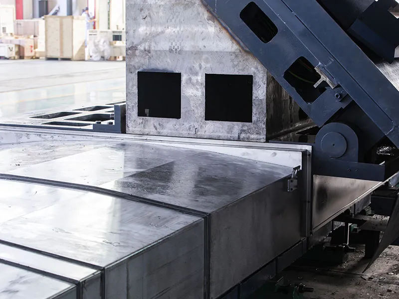
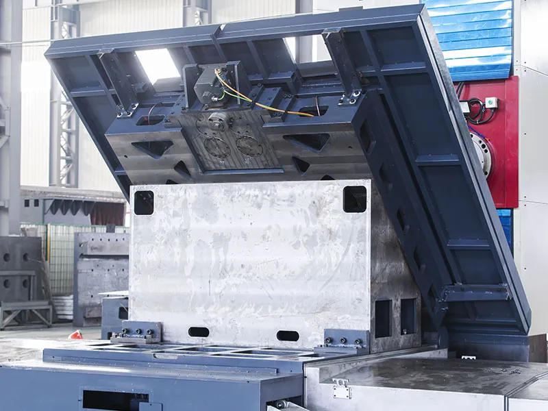
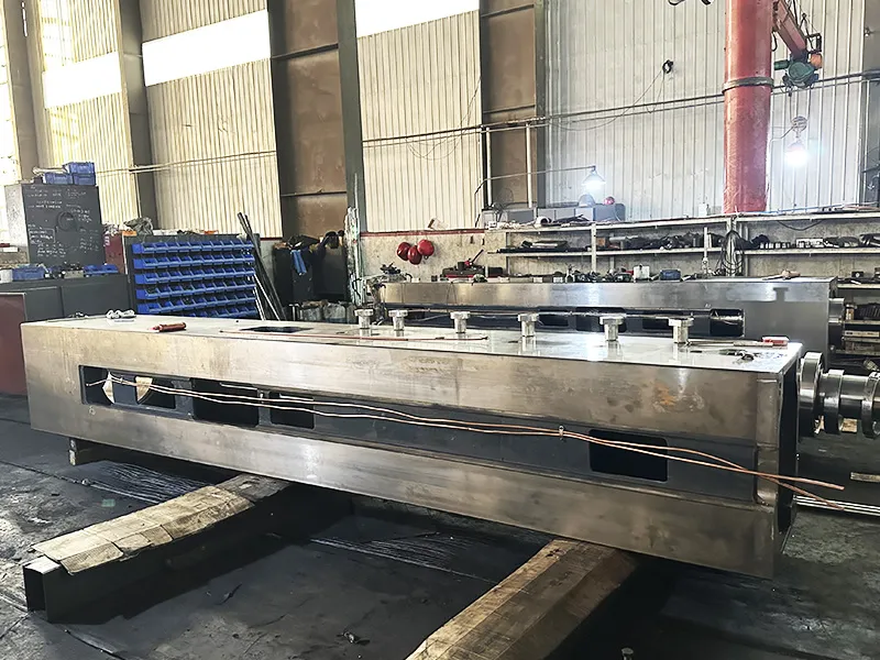
- Basic Large Parts
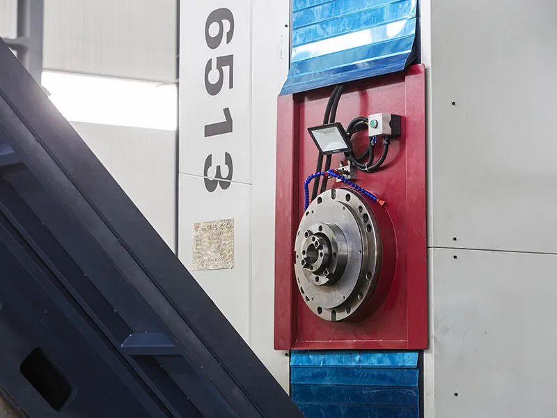
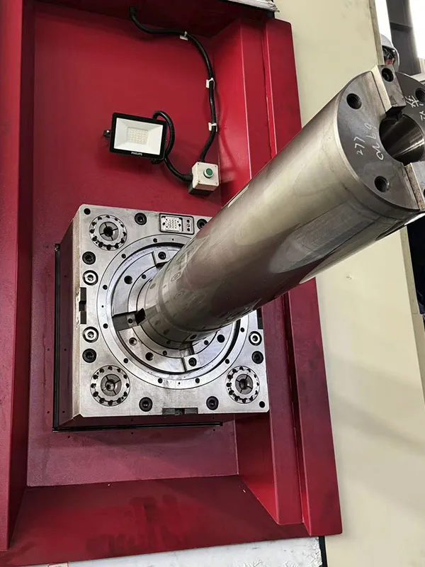
- Spindle
- Double Gear Gap Eliminating Device
- Guideways
- Feed Mechanism
- Counterweight Balanced Ram Saddle and Ram (for models with ram)
- Hydraulic System
- Lubrication System
- CNC System
- Detection Components
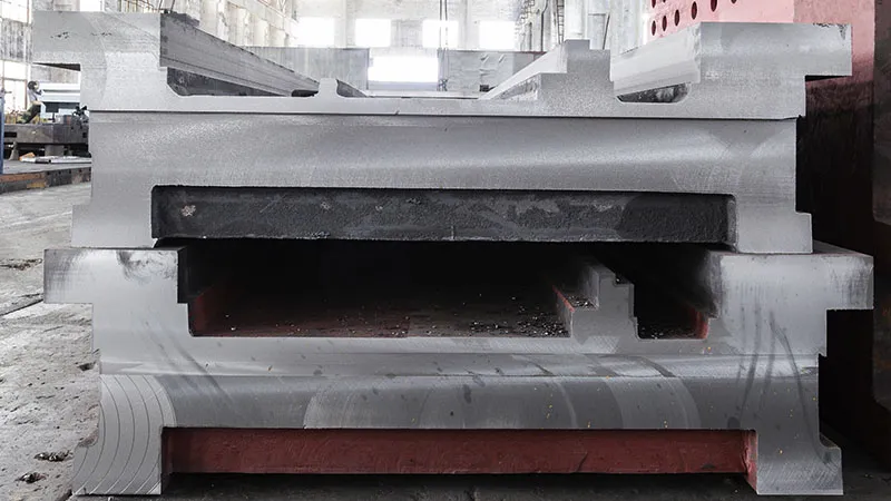
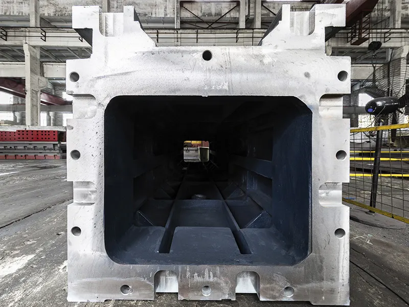
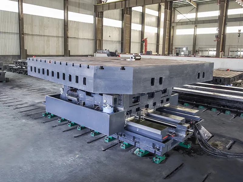
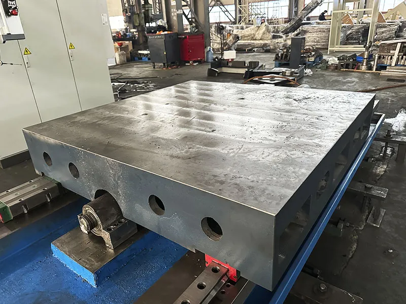
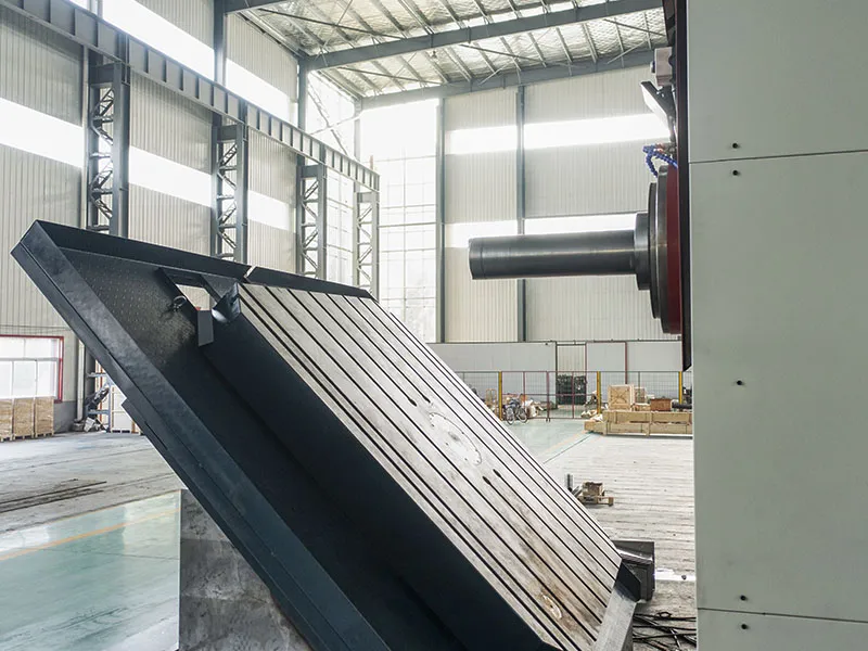
The machine bed, column, worktable, sliding carriage, and tailstock are all made from high-strength resin sand gray cast iron. The ram saddle and ram (if applicable by model) are made from high-grade ductile iron. All these major castings undergo two heat treatment (thermal aging) processes.
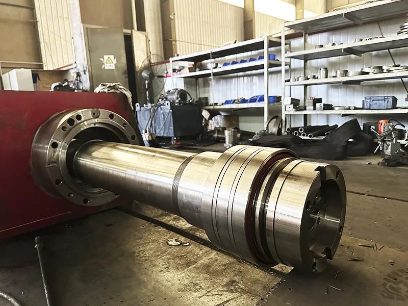
The spindle consists of a boring spindle and a milling spindle, using imported spindle bearings. The main drive system employs an AC servo motor combined with a two-stage mechanical transmission to achieve stepless speed regulation. The spindle material is 38CrMoAlA, surface-nitrided, ground, and polished to a final hardness exceeding HV900.
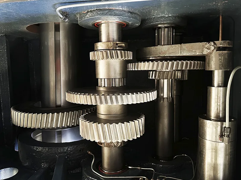
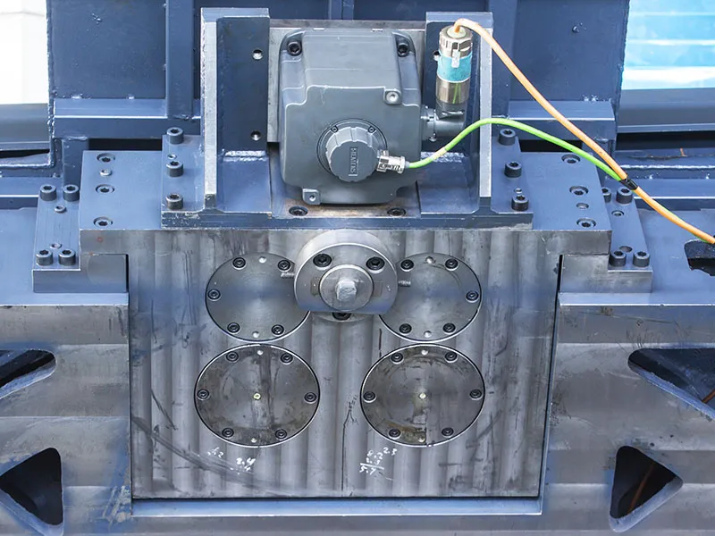
This device allows for arbitrary angle positioning. The rotary axis uses double-row cylindrical roller bearings, with a central unloading device on the upper part of the axis system. The rotary feed mechanism is driven by an AC servo motor, which actuates a large gear ring via a backlash-eliminating reducer and double gears. This structure automatically eliminates gear transmission backlash, ensuring high transmission accuracy. During machining, hydraulic floating clamping is used for reliable and convenient operation, guaranteeing the stability of the oil film thickness.
The X, Y, Z, V, and W coordinate axes feed mechanisms are driven by AC servo motors. They consist of precision zero-backlash reduction gearboxes and preloaded double-nut ball screw pairs, effectively eliminating reverse backlash.
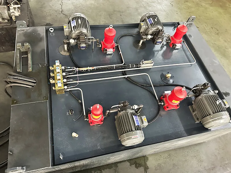
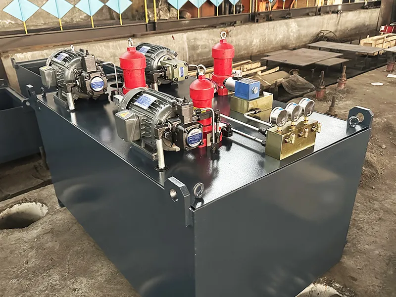
One hydraulic station, equipped with a constant temperature oil cooler, handles the lubrication and cooling of the headstock and spindle. Another hydraulic station serves functions such as spindle speed change, tool release, and rotary table clamping. If hydrostatic guideways are selected, they share a hydraulic station with the headstock cooling system for hydraulic oil supply. All hydraulic components meet international standards for installation dimensions.
The X, Y, Z, B, V, and W coordinate guideways and ball screw nut pairs are lubricated by a timed, quantitative automatic lubrication device. The spindle transmission gears and bearings are lubricated by circulating cooling oil. The spindle front bearings and screw bearings are lubricated with grease.
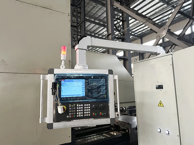
The CNC system can provide six-axis control with arbitrary four-axis linkage. It includes a handheld control unit with a display. The system can also control and manage optional accessories such as a face plate (U-axis), tool magazine, and probes.
Grating scales are used for the X, Y, and W axes, and a circular grating is used for the B-axis, constituting a full closed-loop position detection system. Encoders are used for the V and Z axes, forming a semi-closed-loop position detection system (this is an optional configuration).
Besides traditional boring and milling functions, CNC planer type boring and milling machines can also perform planing operations, making them suitable for multi-sided and large-area machining. The worktable of a CNC planer type boring and milling machine is typically larger, capable of handling heavier workpieces, and thus suitable for heavy machinery component processing.
Shipbuilding involves processing extra-long and heavy components. CNC planer type boring and milling machines, with their long travel and high stability, can machine large-sized, heavy parts. These machines also offer multiple functions like milling, planing, and boring, enabling the processing of complex-shaped parts, reducing machining steps, and improving production efficiency.