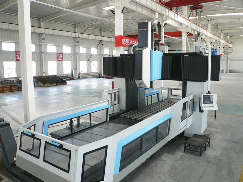
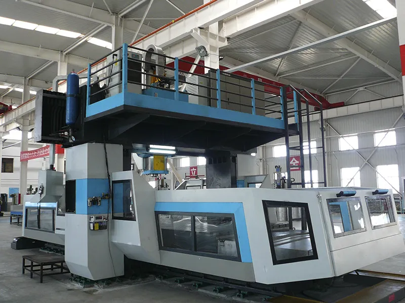
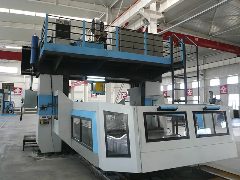
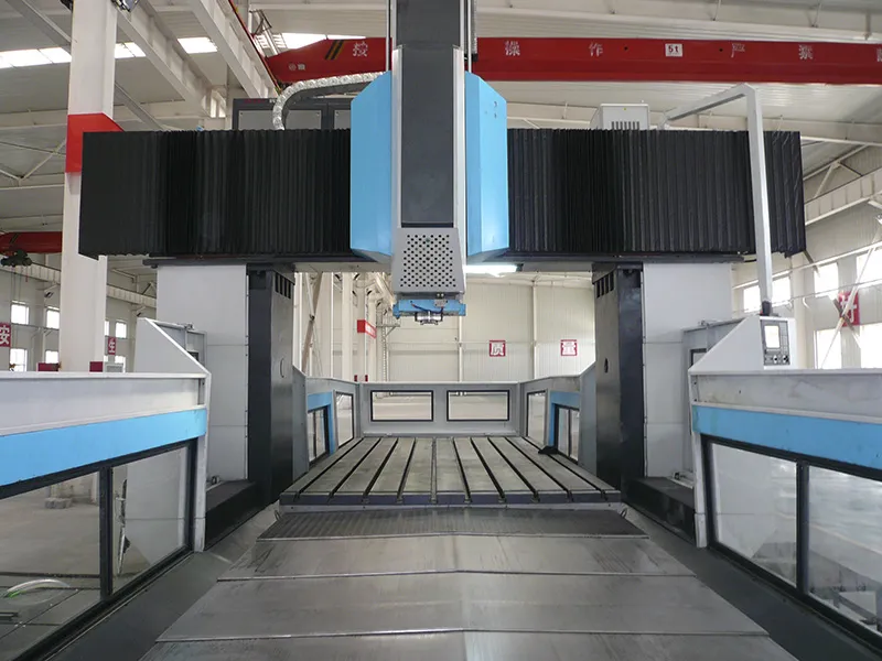
Qingdao Huiteng Machinery Equipment Co., Ltd. (CHTEM)
  • 
  • Home
  • Products +
  • Sectors +
  • Case Studies
  • About Us +
  • Contact
  • Videos
  • Products
  • CNC Gantry Boring and Milling Machine
  • Fixed Gantry & Moving Table Type
CNC GANTRY BORING MILLS

CNC Gantry Boring and Milling Machine, Fixed Gantry & Moving Table Type

Fixed Gantry & Moving Table Type
  • Fixed Gantry & Moving Table Type
  • Fixed Gantry & Moving Table Type
  • Fixed Gantry & Moving Table Type
  • Fixed Gantry & Moving Table Type
  • Fixed Gantry & Moving Table Type
  • Fixed Gantry & Moving Table Type
Portal boring mills for machining of large complex workpieces through boring, milling, drilling, tapping, and other operations

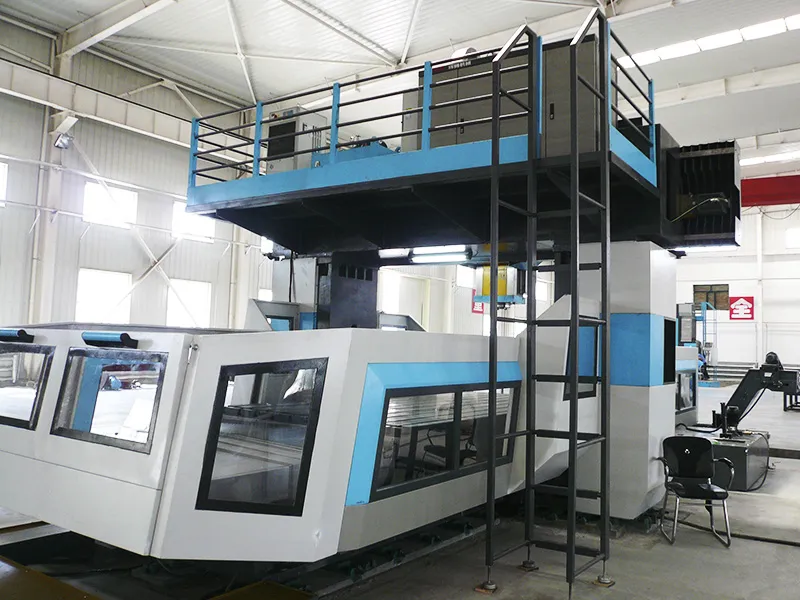
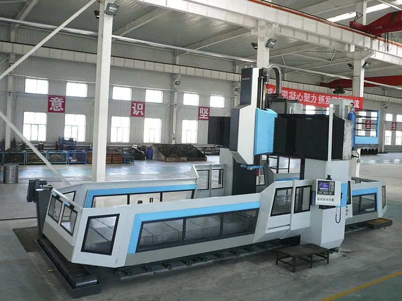
CNC fixed gantry machine can satisfy the rough and fine machining requirements for common milling, drilling, tapping, and boring of internal holes, external circles, planes, steps, conical surfaces, spherical surfaces, grooves, and 2D or 3D complex curved surfaces on various materials such as high-temperature alloys, titanium alloys, heat-resistant alloys, stainless steel, cast iron, and cast steel, including castings, forgings, and raw blanks.

The equipment is equipped with a single high-power boring and milling head on the crossbeam and features three CNC feed axes (X-axis - work platform, Y-axis - boring/milling head, and Z-axis - spindle), capable of two-axis or three-axis linkage. The X-axis dimension of the worktable can be designed according to customer requirements. The gantry width (Y-axis) does not exceed 8 meters, the height does not exceed 6 meters, and the square ram size is not less than 400x400mm.

The rotary motion of the boring/milling head spindle is driven by a spindle motor, and each feed axis is driven by an AC servo motor. A fixed-stroke, quantitative lubrication system is employed. The oil pump station for hydraulic and hydrostatic slide systems is equipped with a temperature control device.

Request a Quote
Applications

This machine is used for multi-variety, small to medium batch processing of precision complex parts in medium to large-scale automotive cold stamping die manufacturing, as well as in the aerospace and equipment manufacturing industries. It satisfies the rough and fine machining requirements for common milling, drilling, tapping, and boring operations on internal holes, external circles, planes, steps, conical surfaces, spherical surfaces, grooves, and 2D or 3D complex curved surfaces made from various materials such as high-temperature alloys, titanium alloys, heat-resistant alloys, stainless steel, cast iron, and cast steel (castings, forgings, raw blanks).

Features
The boring/milling head and ram utilize preloaded ball screw nut transmission pairs for movement. The worktable and boring head movements use high-linearity guide rails, ensuring high precision and rigidity.
The bed guideways are protected by metal telescopic covers, while the crossbeam guideways use accordion-type retractable protective covers.
Worktable movement (X-axis) is driven by a preloaded double-nut ball screw pair. Each feed axis end is limited by a three-contact switch, with an electrical soft limit providing double insurance.
Castings employ a box-type structure, optimized through Finite Element Method (FEM) analysis for good rigidity.
The three-axis feed system uses a direct-link drive with pre-tightened and stretched installation.
A large cross-section square ram (available in 500x500mm and 600x600mm sizes) allows for powerful cutting.
A German ZF dual-speed precision gearbox directly drives the spindle, enabling high-speed, high-power cutting.
Model Options
Model Distance Between Columns (mm) Max. Load Capacity of Worktable (T)
GMH2412/2112 1800 2
GMH2416/2116 2200 5
GMH2420/2120 2600 5
GMH2425/2125 3100 8
GMH2430/2130 3600 8
GMH2435/2135 4100 8
GMH2440/2140 4600 10
Specifications Working Area Worktable Travel (X-Axis) | Worktable length + stroke of 300-500mm
  • GMH2412/GMH2112
  • GMH2416/GMH2116
  • GMH2420/GMH2120
  • GMH2425/GMH2125
  • GMH2430/GMH2130
  • GMH2435/GMH2135
  • GMH2440/GMH2140
Worktable Size Width mm 1250
Worktable Size Length mm 2500 (select length in sections of 1000mm)
Working Area Worktable Travel (X-Axis) mm Worktable length + stroke of 300-500mm
Working Area Headstock Travel (Y-Axis) mm 2400
Working Area Ram Travel (Z-Axis) mm 1000
Working Area Crossbeam Travel (W-Axis) (for GMH21 series only) mm 1500
Distance Between Columns mm 1800
Spindle Nose to Worktable Surface mm 200
Ram Cross Section mm 400×380
Max. Load Capacity of Worktable t/m² 2
Feed Rate X-Axis mm/min 5-6000
Feed Rate Y-Axis mm/min 5-6000
Feed Rate Z-Axis mm/min 5-4000
Spindle Taper mm BT50
Spindle Speed mm/min 2-6000
Spindle Power kw 30
Worktable Size Width mm 1600
Worktable Size Length mm 2500 (select length in sections of 1000mm)
Working Area Worktable Travel (X-Axis) mm Worktable length + stroke of 300-500mm
Working Area Headstock Travel (Y-Axis) mm 2800
Working Area Ram Travel (Z-Axis) mm 1000
Working Area Crossbeam Travel (W-Axis) (for GMH21 series only) mm 2000
Distance Between Columns mm 2200
Spindle Nose to Worktable Surface mm 200
Ram Cross Section mm 400×380
Max. Load Capacity of Worktable t/m² 5
Feed Rate X-Axis mm/min 5-6000
Feed Rate Y-Axis mm/min 5-6000
Feed Rate Z-Axis mm/min 5-4000
Spindle Taper mm BT50
Spindle Speed mm/min 2-6000
Spindle Power kw 30
Worktable Size Width mm 2000
Worktable Size Length mm 2500 (select length in sections of 1000mm)
Working Area Worktable Travel (X-Axis) mm Worktable length + stroke of 300-500mm
Working Area Headstock Travel (Y-Axis) mm 3200
Working Area Ram Travel (Z-Axis) mm 1000
Working Area Crossbeam Travel (W-Axis) (for GMH21 series only) mm 2000
Distance Between Columns mm 2600
Spindle Nose to Worktable Surface mm 200
Ram Cross Section mm 400×380
Max. Load Capacity of Worktable t/m² 5
Feed Rate X-Axis mm/min 5-6000
Feed Rate Y-Axis mm/min 5-6000
Feed Rate Z-Axis mm/min 5-4000
Spindle Taper mm BT50
Spindle Speed mm/min 2-6000
Spindle Power kw 37
Worktable Size Width mm 2500
Worktable Size Length mm 2500 (select length in sections of 1000mm)
Working Area Worktable Travel (X-Axis) mm Worktable length + stroke of 300-500mm
Working Area Headstock Travel (Y-Axis) mm 3700
Working Area Ram Travel (Z-Axis) mm 1000
Working Area Crossbeam Travel (W-Axis) (for GMH21 series only) mm 2000
Distance Between Columns mm 3100
Spindle Nose to Worktable Surface mm 200
Ram Cross Section mm 400×380
Max. Load Capacity of Worktable t/m² 8
Feed Rate X-Axis mm/min 5-6000
Feed Rate Y-Axis mm/min 5-6000
Feed Rate Z-Axis mm/min 5-4000
Spindle Taper mm BT50
Spindle Speed mm/min 2-6000
Spindle Power kw 37
Worktable Size Width mm 3000
Worktable Size Length mm 2500 (select length in sections of 1000mm)
Working Area Worktable Travel (X-Axis) mm Worktable length + stroke of 300-500mm
Working Area Headstock Travel (Y-Axis) mm 4200
Working Area Ram Travel (Z-Axis) mm 1250
Working Area Crossbeam Travel (W-Axis) (for GMH21 series only) mm 2500
Distance Between Columns mm 3600
Spindle Nose to Worktable Surface mm 200
Ram Cross Section mm 500×500
Max. Load Capacity of Worktable t/m² 8
Feed Rate X-Axis mm/min 5-6000
Feed Rate Y-Axis mm/min 5-6000
Feed Rate Z-Axis mm/min 5-4000
Spindle Taper mm BT50
Spindle Speed mm/min 2-4000
Spindle Power kw 37
Worktable Size Width mm 3500
Worktable Size Length mm 2500 (select length in sections of 1000mm)
Working Area Worktable Travel (X-Axis) mm Worktable length + stroke of 300-500mm
Working Area Headstock Travel (Y-Axis) mm 4800
Working Area Ram Travel (Z-Axis) mm 1250
Working Area Crossbeam Travel (W-Axis) (for GMH21 series only) mm 2500
Distance Between Columns mm 4100
Spindle Nose to Worktable Surface mm 200
Ram Cross Section mm 500×500
Max. Load Capacity of Worktable t/m² 8
Feed Rate X-Axis mm/min 5-6000
Feed Rate Y-Axis mm/min 5-6000
Feed Rate Z-Axis mm/min 5-4000
Spindle Taper mm BT50
Spindle Speed mm/min 2-4000
Spindle Power kw 60
Worktable Size Width mm 4000
Worktable Size Length mm 2500 (select length in sections of 1000mm)
Working Area Worktable Travel (X-Axis) mm Worktable length + stroke of 300-500mm
Working Area Headstock Travel (Y-Axis) mm 5300
Working Area Ram Travel (Z-Axis) mm 1250
Working Area Crossbeam Travel (W-Axis) (for GMH21 series only) mm 2500
Distance Between Columns mm 4600
Spindle Nose to Worktable Surface mm 200
Ram Cross Section mm 500×500
Max. Load Capacity of Worktable t/m² 10
Feed Rate X-Axis mm/min 5-6000
Feed Rate Y-Axis mm/min 5-6000
Feed Rate Z-Axis mm/min 5-4000
Spindle Taper mm BT50
Spindle Speed mm/min 2-4000
Spindle Power kw 60
What are the differences between a fixed gantry boring and milling machine and other machine types (e.g., horizontal, vertical)?
Applicable Workpieces Fixed gantry boring and milling machines are more suitable for processing large, heavy workpieces, especially long or wide parts.
Machining Accuracy Due to their high rigidity and stability, fixed gantry boring and milling machines can maintain high machining accuracy under heavy loads.
Worktable Load Typically, the worktable of a fixed gantry boring and milling machine has a strong load-bearing capacity, making it suitable for processing heavy workpieces.
In multi-variety, small to medium batch processing, how does a fixed gantry boring and milling machine handle the diversity of workpiece sizes and materials?
Through the flexibility of its CNC system, the machine can easily adjust processing methods and motion trajectories for different workpieces, adapting to various sizes and shapes.
With appropriate tool selection, it can effectively process workpieces of various materials.
Processing parameters such as feed rate, cutting depth, and spindle speed can be adjusted according to the characteristics of different materials.
It can be equipped with an efficient cooling system to reduce the impact of cutting heat on materials and precision.
What automation features do fixed gantry boring and milling machines offer for processing medium to large automotive cold stamping dies?
Automatic Tool Changer (ATC) System These machines are often equipped with an ATC system that can automatically change tools according to different processing needs, reducing manual operations and improving efficiency.
Automatic Measurement and Monitoring System Some high-end models can be equipped with automatic measurement systems for in-process inspection of die parts, allowing real-time adjustment of processing parameters to ensure die accuracy.
Automatic Loading/Unloading System In mass production scenarios, an automatic loading/unloading system can enhance production efficiency and reduce manual intervention.
Not sure how to choose the right CNC boring and milling machine?
We are happy to help you
E-mail: 13864207010@163.com
Get in Touch
See Other Machines
  • Moving Gantry & Fixed Table Type
    Moving Gantry & Fixed Table Type
  • CNC Floor Type Boring and Milling Machine
    CNC Floor Type Boring and Milling Machine
  • CNC Table Type Boring and Milling Machine
    CNC Table Type Boring and Milling Machine
  • CNC Planer Type Boring and Milling Machine
    CNC Planer Type Boring and Milling Machine
Products
  • CNC Floor Type Boring and Milling Machine
  • CNC Table Type Boring and Milling Machine
  • CNC Planer Type Boring and Milling Machine
  • CNC Gantry Boring and Milling Machine
Sectors
  • Mining Machinery
  • Energy Equipment
  • Shipbuilding
  • Engine
  • Aerospace & Aircraft
  • Construction Machinery
  • Forging Equipment
About Us
  • Company Profile
  • Capabilities
  • Service
  • FAQs
Contact Us
13864207010@163.com
Mr. Jiang Dong
+86-13864207010
Supported by ETW International Inc. USA