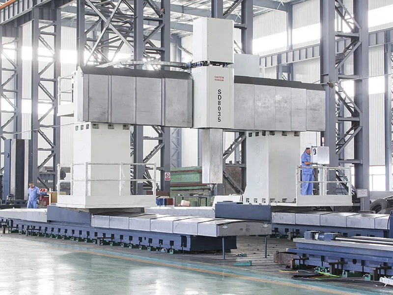
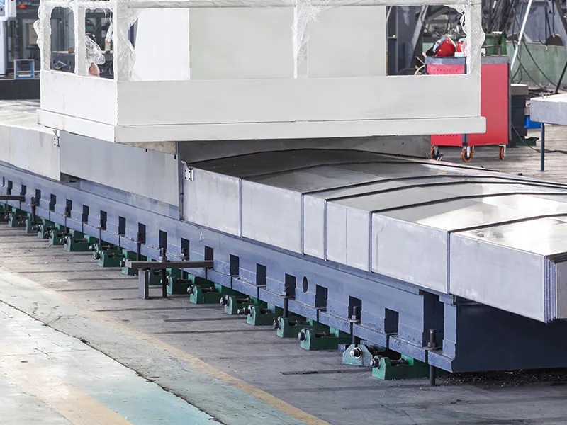
Qingdao Huiteng Machinery Equipment Co., Ltd. (CHTEM)
  • 
  • Home
  • Products +
  • Sectors +
  • Case Studies
  • About Us +
  • Contact
  • Videos
  • Products
  • CNC Gantry Boring and Milling Machine
  • Moving Gantry & Fixed Table Type
Moving Gantry & Fixed Table Type
  • Moving Gantry & Fixed Table Type
  • Moving Gantry & Fixed Table Type
  • Moving Gantry & Fixed Table Type
CNC GANTRY BORING MILLS

CNC Gantry Boring and Milling Machine, Moving Gantry & Fixed Table Type

Portal boring mills for machining of large complex workpieces through boring, milling, drilling, tapping, and other operations

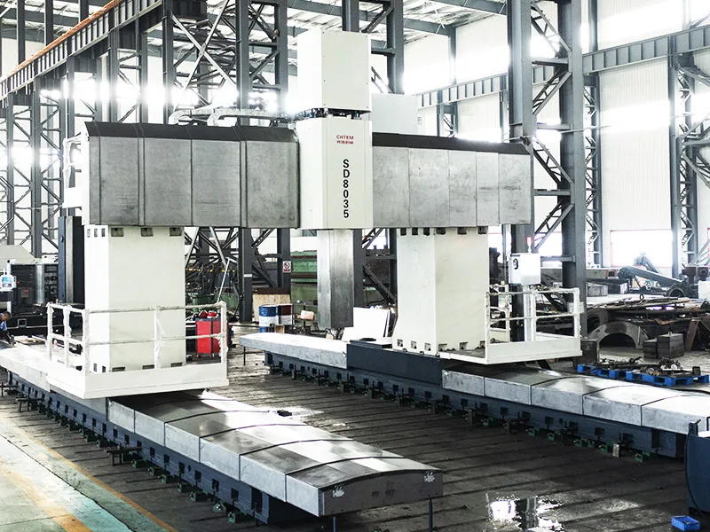
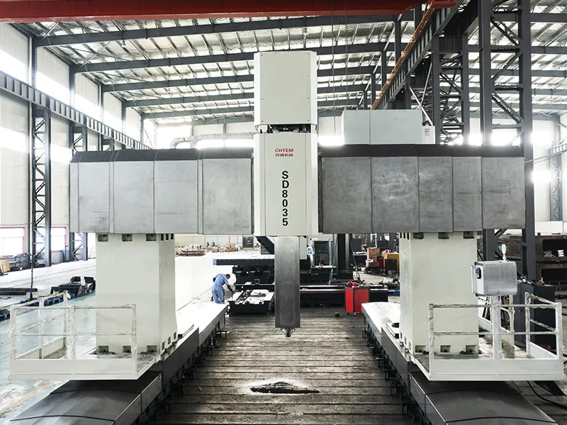
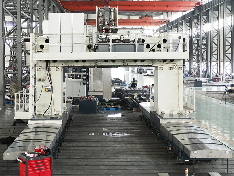
This machine is engineered for comprehensive machining of large and intricate workpieces, performing precise boring, milling, drilling, tapping, and other essential operations. Featuring three CNC controlled feed axes (X, Y, Z), it achieves simultaneous three-axis(linkage) for efficient milling, boring, and drilling, including rigid tapping and contour milling.

Capable of handling a wide range of machining tasks, the available automatic tool changer and various optional interchangeable attachment heads enable five-sided machining in a single workpiece setup, maximizing efficiency and accuracy. The X-axis travel can be customized to meet specific customer requirements. The gantry width (Y-axis) extends up to 8 meters, with a height capacity of up to 6 meters, and a robust ram size starting from 400x400mm. The machine's spindle and feed drives utilize a SIEMENS series full digital drive system and servo motors for superior performance.

Request a Quote
Applications

Ideally suited for multi-variety, small to medium batch processing of precision and complex parts in medium and large automotive cold stamping dies, as well as the aerospace and equipment manufacturing industries. Engineered to perform common milling, drilling, tapping, and boring operations, including machining internal holes, external diameters, planes, steps, tapers, spheres, grooves, and intricate 2D or 3D curved surfaces on various high-temperature alloys, titanium alloys, heat-resistant alloys, stainless steel, cast iron, and cast steel forgings and blanks for both roughing and finishing operations.

  • Moving Gantry & Fixed Table Type
  • Moving Gantry & Fixed Table Type
  • Moving Gantry & Fixed Table Type
  • Moving Gantry & Fixed Table Type
  • Moving Gantry & Fixed Table Type
  • Moving Gantry & Fixed Table Type
  • Moving Gantry & Fixed Table Type
  • Moving Gantry & Fixed Table Type
Features
The multi-system display provides comprehensive information and a dynamic machining path visualization for user-friendly operation.
The real-time ladder diagram monitoring page offers significant convenience for maintenance procedures.
Employs a digital servo system that compensates for mechanical errors in the transmission system through stored pitch error compensation and backlash compensation functions.
Utilizes high-resolution position detectors and high-speed microprocessor-based software servo control functions to achieve high-speed and high-precision servo control.
Full enclosure guarding and a chain-type automatic chip conveyor ensure safe and easy operation and efficient chip removal.
CNC system options include German SIEMENS 828DsI, Japanese FANUC 0Im, and Spanish FAGOR 8055.
Both the Y and W axes feature preloaded double nut ball screw pairs for transmission.
The X-axis utilizes a backlash-free dual pinion drive system engaging with a precision rack for movement. Both gears and racks are hardened, high-precision, and ground for optimal performance.
Model Options
Model Distance Between Columns (mm) Pass Height (mm) Max. Load Capacity of Worktable (T)
XKH2825/2725
GMH2825/2725
3200 2500 15
XKH2830/2730
GMH2830/2730
3600 3000 15
XKH2835/2735
GMH2835/2735
4200 3500 20
XKH2840/2740
GMH2840/2740
4600 4000 20
XKH2845/2745
GMH2845/2745
5200 4500 20
XKH2850/2750
GMH2850/2750
5600 5000 20
Specifications Working Area Gantry Travel (X-Axis) | Worktable length + stroke of 500mm
  • XKH2825/XKH2725
    GMH2825/GMH2725
  • XKH2830/XKH2730
    GMH2830/GMH2730
  • XKH2835/XKH2735
    GMH2835/GMH2735
  • XKH2840/XKH2740
    GMH2840/GMH2740
  • XKH2845/XKH2745
    GMH2845/GMH2745
  • XKH2850/XKH2750
    GMH2850/GMH2750
Worktable Size Width mm 2500
Worktable Size Length mm 8000 (select length in sections of 1000mm)
Working Area Gantry Travel (X-Axis) mm Worktable length + stroke of 500mm
Working Area Headstock Travel (Y-Axis) mm 3600
Working Area Ram Travel (Z-Axis) mm 1250
Working Area Crossbeam Travel (W-Axis) (for XK28 series only) mm 2000
Distance Between Columns mm 3200
Spindle Nose to Worktable Surface mm 200
Ram Cross Section mm 500×500
Max. Load Capacity of Worktable t/m² 15
Feed Rate X-Axis mm/min 5-6000
Feed Rate Y-Axis mm/min 5-6000
Feed Rate Z-Axis mm/min 5-4000
Feed Rate W-Axis mm/min 5-2000
Spindle Taper  mm BT50
Spindle Speed mm/min 2-2000
Spindle Power kw 37
Worktable Size Width mm 3000
Worktable Size Length mm 8000 (select length in sections of 1000mm)
Working Area Gantry Travel (X-Axis) mm Worktable length + stroke of 500mm
Working Area Headstock Travel (Y-Axis) mm 4200
Working Area Ram Travel (Z-Axis) mm 1250
Working Area Crossbeam Travel (W-Axis) (for XK28 series only) mm 2000
Distance Between Columns mm 3600
Spindle Nose to Worktable Surface mm 200
Ram Cross Section mm 500×500
Max. Load Capacity of Worktable t/m² 15
Feed Rate X-Axis mm/min 5-6000
Feed Rate Y-Axis mm/min 5-6000
Feed Rate Z-Axis mm/min 5-4000
Feed Rate W-Axis mm/min 5-2000
Spindle Taper  mm BT50
Spindle Speed mm/min 2-2000
Spindle Power kw 37
Worktable Size Width mm 3500
Worktable Size Length mm 8000 (select length in sections of 1000mm)
Working Area Gantry Travel (X-Axis) mm Worktable length + stroke of 500mm
Working Area Headstock Travel (Y-Axis) mm 4800
Working Area Ram Travel (Z-Axis) mm 1500
Working Area Crossbeam Travel (W-Axis) (for XK28 series only) mm 2500
Distance Between Columns mm 4200
Spindle Nose to Worktable Surface mm 200
Ram Cross Section mm 500×500
Max. Load Capacity of Worktable t/m² 20
Feed Rate X-Axis mm/min 5-6000
Feed Rate Y-Axis mm/min 5-6000
Feed Rate Z-Axis mm/min 5-4000
Feed Rate W-Axis mm/min 5-2000
Spindle Taper  mm BT50
Spindle Speed mm/min 2-1500
Spindle Power kw 60
Worktable Size Width mm 4000
Worktable Size Length mm 8000 (select length in sections of 1000mm)
Working Area Gantry Travel (X-Axis) mm Worktable length + stroke of 500mm
Working Area Headstock Travel (Y-Axis) mm 5200
Working Area Ram Travel (Z-Axis) mm 1500
Working Area Crossbeam Travel (W-Axis) (for XK28 series only) mm 2500
Distance Between Columns mm 4600
Spindle Nose to Worktable Surface mm 200
Ram Cross Section mm 600×600
Max. Load Capacity of Worktable t/m² 20
Feed Rate X-Axis mm/min 5-6000
Feed Rate Y-Axis mm/min 5-6000
Feed Rate Z-Axis mm/min 5-4000
Feed Rate W-Axis mm/min 5-2000
Spindle Taper  mm BT50
Spindle Speed mm/min 2-1500
Spindle Power kw 60
Worktable Size Width mm 4500
Worktable Size Length mm 8000 (select length in sections of 1000mm)
Working Area Gantry Travel (X-Axis) mm Worktable length + stroke of 500mm
Working Area Headstock Travel (Y-Axis) mm 5800
Working Area Ram Travel (Z-Axis) mm 1500
Working Area Crossbeam Travel (W-Axis) (for XK28 series only) mm 2500
Distance Between Columns mm 5200
Spindle Nose to Worktable Surface mm 200
Ram Cross Section mm 600×600
Max. Load Capacity of Worktable t/m² 20
Feed Rate X-Axis mm/min 5-6000
Feed Rate Y-Axis mm/min 5-6000
Feed Rate Z-Axis mm/min 5-4000
Feed Rate W-Axis mm/min 5-2000
Spindle Taper  mm BT50
Spindle Speed mm/min 2-1500
Spindle Power kw 100
Worktable Size Width mm 5000
Worktable Size Length mm 8000 (select length in sections of 1000mm)
Working Area Gantry Travel (X-Axis) mm Worktable length + stroke of 500mm
Working Area Headstock Travel (Y-Axis) mm 6300
Working Area Ram Travel (Z-Axis) mm 1500
Working Area Crossbeam Travel (W-Axis) (for XK28 series only) mm 2500
Distance Between Columns mm 5600
Spindle Nose to Worktable Surface mm 200
Ram Cross Section mm 600×600
Max. Load Capacity of Worktable t/m² 20
Feed Rate X-Axis mm/min 5-6000
Feed Rate Y-Axis mm/min 5-6000
Feed Rate Z-Axis mm/min 5-4000
Feed Rate W-Axis mm/min 5-2000
Spindle Taper  mm BT50
Spindle Speed mm/min 2-1500
Spindle Power kw 100
Main Components
The machine adopts a layout with a fixed worktable and a moving gantry frame. The gantry frame moves horizontally along the machine bed guideways (X-axis), the ram saddle moves horizontally along the crossbeam guideways (Y-axis), and the ram slides vertically along the saddle guideways (Z-axis).
X-Axis Guideways Employ hydrostatic guideways or heavy-duty roller linear guideways, characterized by a low friction coefficient, smooth low-speed movement without stick-slip, and high positioning accuracy. Utilizes dual-motor, dual-pinion synchronous drive technology for superior servo drive performance; also offers high load-bearing capacity and excellent vibration damping during cutting, enhancing the machine's accuracy, stability, and service life.
Y-Axis Guideways Employ hydrostatic guideways or heavy-duty roller linear guideways. The crossbeam features a large cross-section and a stepped guideway arrangement, providing sufficient bending and torsional rigidity. Utilizes dual-motor, dual-pinion synchronous drive technology for superior servo drive performance; offers high cutting force resistance, improving the machine's accuracy and long-term precision stability.
Z-Axis Guideways The guideway pair is a sliding guideway pair (cast iron-plastic friction pair). This design offers good shock absorption, ensuring smooth cutting during machining. Employs a servo motor driving a ball screw through a reducer, providing high precision and strong stability.
What factors should be considered when selecting a suitable CNC moving gantry & fixed table type boring and milling machine for shipbuilding?
Machining Size and Weight Requirements Select appropriate machine specifications and load-bearing capacity based on the dimensions and weight of ship parts.
Machining Accuracy Requirements Choose a machine with high precision and stability to meet the accuracy demands of ship components.
Automation Needs If increased production efficiency is required, consider machines equipped with automatic tool changers and automatic loading/unloading systems.
Machine Structure Rigidity Opt for a machine with high rigidity to ensure stability and accuracy during the machining process.
How does a CNC moving gantry & fixed table type boring and milling machine enhance production efficiency in mold manufacturing?
The machine can complete multiple processes in a single clamping, reducing the number of times the workpiece needs to be reclamped and improving production efficiency.
The automatic tool changer system can automatically select tools according to machining needs, reducing manual operation time and increasing machining efficiency.
The machine features high cutting speeds and feed rates, which can effectively improve the production efficiency of large batches of mold parts.
The CNC system can monitor the machining status in real time and automatically adjust machining parameters, minimizing human errors and improving production efficiency.
Not sure how to choose the right CNC boring and milling machine?
We are happy to help you
E-mail: 13864207010@163.com
Get in Touch
See Other Machines
  • CNC Floor Type Boring and Milling Machine
    CNC Floor Type Boring and Milling Machine
  • CNC Table Type Boring and Milling Machine
    CNC Table Type Boring and Milling Machine
  • CNC Planer Type Boring and Milling Machine
    CNC Planer Type Boring and Milling Machine
  • Fixed Gantry & Moving Table Type
    Fixed Gantry & Moving Table Type
Products
  • CNC Floor Type Boring and Milling Machine
  • CNC Table Type Boring and Milling Machine
  • CNC Planer Type Boring and Milling Machine
  • CNC Gantry Boring and Milling Machine
Sectors
  • Mining Machinery
  • Energy Equipment
  • Shipbuilding
  • Engine
  • Aerospace & Aircraft
  • Construction Machinery
  • Forging Equipment
About Us
  • Company Profile
  • Capabilities
  • Service
  • FAQs
Contact Us
13864207010@163.com
Mr. Jiang Dong
+86-13864207010
Supported by ETW International Inc. USA